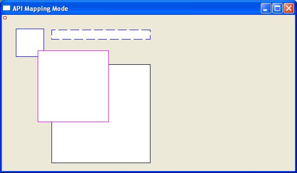
The mapping mode governs how Windows translates logical coordinates into device coordinates within the current device context. Logical coordinates represent the graphics and text application values and the device coordinates are the resulting pixel positions within a window. The mapping mode also determines the orientation of the X-axis and the Y-axis and whether the values of X and Y increase or decrease in respect to the origin. The default device context sets logical units the same as pixels with the X-axis being right positive, the Y-axis being positive down, and sets the coordinate origin to the upper left corner of the window. The 8 different mapping modes are listed below
| Mapping Mode | Logical Unit | x-axis and y-axis |
| MM_TEXT | Pixel | Positive x is to the right; positive y is down |
| MM_LOMETRIC | 0.1 mm | Positive x is to the right;positive y is up. |
| MM_HIMETRIC | 0.01 mm | Positive x is to the right;positive y is up. |
| MM_LOENGLISH | 0.01 in | Positive x is to the right; positive y is up. |
| MM_HIENGLISH | 0.001 in | Positive x is to the right; positive y is up. |
| MM_TWIPS | 1/1440 in | Positive x is to the right; positive y is up. |
| MM_ISOTROPIC | user specified | user specified |
| MM_ANISOTROPIC | user specified | user specified |
To select a different mapping mode, use the function SetMapMode()-
int SetMapMode(HDC hdc,int iMode);
where
hdc – A handle to the device context.
iMode – The new mapping mode.
If the function succeeds, the return is previous mapping mode. If the function fails, the return value is zero.
The MM_ISOTROPIC and MM_ANISOTROPIC mapping modes differ from the other mapping modes in that the unit of measure used to transform logical coordinates to device coordinates can be set by the user. The MM_ISOTROPIC and MM_ANISOTROPIC mapping modes differ from each other is that with the former, the range of the x-axis and y-axis must be the same, and with the latter, the range of the x-axis and y-axis can be different. Selecting either of these modes means the developer will need to set the dimensions of the window.
To set the logical extents of the window associated with the device context use the SetWindowExtEx() function. To map the corresponding device size, known as the viewpoint onto these logical coordinates use the SetViewportExtEx() member function.
Sets the horizontal and vertical extents of the window for a device context by using the specified values.
BOOL SetWindowExtEx( HDC hdc, int x, int y, LPSIZE lpsz );
hdc – A handle to the device context.
x – The window’s horizontal extent in logical units.
y – The window’s vertical extent in logical units.
lpsz – A pointer to a SIZE structure that receives the previous window extents, in logical units. If lpSize is NULL, this parameter is not used.
If the function succeeds, the return value is nonzero. Else the return value is zero.
sets the horizontal and vertical extents of the viewport for a device context by using the specified values.
BOOL SetViewportExtEx( HDC hdc, int x, int y,LPSIZE lpsz);
hdc – A handle to the device context.
x – The horizontal extent, in device units, of the viewport.
y – The vertical extent, in device units, of the viewport.
lpsz – A pointer to a SIZE structure that receives the previous viewport extents, in device units. If lpSize is NULL, this parameter is not used.
If the function succeeds, the return value is nonzero. else the return value is zero.
By default, a device context’s origin, regardless of the mapping mode. is in the upper left corner of the display. This device context’s origin can however be changed by using the API functions SetWindowOrgEx() and SetViewportOrgEx(). The former moves the windows origin, and the latter the viewport origin. The prototype for these functions is -
BOOL SetWindowOrgEx(HDC hdc,int x,int y,LPPOINT lppt);


BOOL SetViewportOrgEx( HDC hdc, int x, int y, LPPOINT lppt);
hdc – A handle to the device context.
x – The x-coordinate of the new viewport origin.
y – The y-coordinate of the new viewport origin.
lppt – A pointer to a POINT structure that receives the previous viewport origin, in device coordinates. If lpPoint is NULL, this parameter is not used.
If the function succeeds, the return value is nonzero. Else if the function fails, the return value is zero.
The following short program draws 5 squares under different mapping to illustrate the different display characteristics of each
#include <windows.h>

LRESULT CALLBACK WndProc(HWND, UINT, WPARAM, LPARAM);

HINSTANCE hInstance;

COLORREF bk_color;

int WINAPI wWinMain(HINSTANCE hInstance, HINSTANCE hPrevInstance,

PWSTR lpCmdLine, int nCmdShow) {

HWND hwnd;

MSG msg ;

WNDCLASS wc = {0};

wc.lpszClassName = TEXT("GroupBox");

wc.hInstance = hInstance;

wc.hbrBackground = GetSysColorBrush(COLOR_3DFACE);

wc.lpfnWndProc = WndProc;

wc.hCursor = LoadCursor(0, IDC_ARROW);

hInstance = hInstance;

RegisterClass(&wc);

hwnd = CreateWindow(wc.lpszClassName, TEXT("API Mapping Mode"),WS_OVERLAPPEDWINDOW | WS_VISIBLE,100, 100, 600, 350, 0, 0, hInstance, 0);

while( GetMessage(&msg, NULL, 0, 0)) {

DispatchMessage(&msg);

}

return (int) msg.wParam;

}

LRESULT CALLBACK WndProc(HWND hwnd, UINT msg,

WPARAM wParam, LPARAM lParam) {

HDC dc;

PAINTSTRUCT ps;


switch(msg) {

case WM_PAINT:

dc = BeginPaint(hwnd, &ps);

RECT rect;

GetClientRect (hwnd,&rect);

//draw rectangle with default pen

Rectangle (dc,100, 100, 300, 300);

//draw rectangle with red pen using mapping mode MM_HIMETRIC

HPEN linecolour;

linecolour=CreatePen(PS_SOLID,1,RGB(255, 0, 0));

SelectObject(dc,linecolour);

SetMapMode (dc,MM_HIMETRIC);

Rectangle (dc,100, -100, 300, -300);

DeleteObject(linecolour);

//draw rectangle with blue pen using mapping mode MM_LOMETRIC

HPEN linecolour1;

linecolour1=CreatePen(PS_SOLID,1,RGB(0, 0, 255));

SelectObject(dc,linecolour1);

SetMapMode (dc,MM_LOMETRIC);

Rectangle (dc,100, -100, 300, -300);

DeleteObject(linecolour1);

//draw rectangle with purple pen using mapping mode MM_LOENGLISH

HPEN linecolour2;

linecolour2=CreatePen(PS_SOLID,1,RGB(255, 0, 255));

SetMapMode (dc,MM_LOENGLISH);

SelectObject(dc,linecolour2);

Rectangle (dc,100, -100, 300, -300);

DeleteObject(linecolour2);

//draw rectangle with blue pen using and PS_DASH pen style using mapping mode MM_ANISOTROPIC

SetMapMode (dc,MM_ANISOTROPIC);

SetWindowExtEx (dc,1, 10,NULL);

SetViewportExtEx (dc,1,1,NULL);

HPEN linecolour3;

linecolour3=CreatePen(PS_DASH,1,RGB(0, 0, 255));

SelectObject(dc,linecolour3);

Rectangle (dc,100, 300, 300, 500);

DeleteObject(linecolour3);

EndPaint(hwnd, &ps);

break;

case WM_DESTROY:

PostQuitMessage(0);

break;

}

return DefWindowProc(hwnd, msg, wParam, lParam);

}